On one of my groups a question was posted about electrical and I just so happen to be doing the wiring on my Christmas Tree shop in a tree stump project at the time so I took pics.
The house itself had already been wired. Each light is 12v bulb that I either inserted through a pony bead or a flower bead. Then the wire went through a hole in the ceiling. The wire was then hidden via grove in the ceiling. This groove then ends up under the flooring. The wires were all brought together on one side of the house and then I soldered the leads from one side of each light to a longer and slightly heavier wire. Repeating this process for the other set of leads.
Now this was all hidden under the tree bark (made of plaster cloth).
When the house was attached to the foam base, I just made a hole in the base and brought the connector wires thru the hole. I then made a groove under the foam base to the side as I had planned to have this connection out that way. But when I got this new case and the house fit perfectly (after a 1/4″ trim to the sides of the base) so I changed what I needed for a groove.
Groove to the left was the before and the groove down the middle is the after. The white spots on the wires is where I had to add to my original leads.
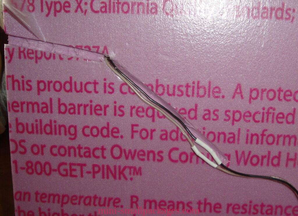
The wires fit in the groove but a piece of paper can be glued to help keep them in place as well. Just glue on the outside of the leads.
This case is a basketball display case so it has a hole in the center of the bottom. It also has another board underneath. This board was brad nailed in so we didn’t want to remove it.
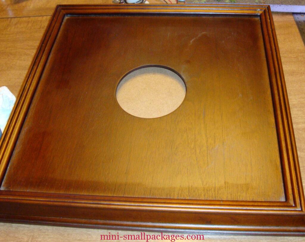
I knew I wanted a switch on this so I determined where my switch and where my wire to the transformer plug will be as well.
I want the switch on the side so I mark a spot for that.
Now I have to drill a hole for it. I used my dremel tool and a drill bit to start. Then I switched to another bit that had extra teeth on it. But my husband told me later I should have used a router bit which is pointed on one end and then curved to the side.
Here’s the hole I made for the switch.
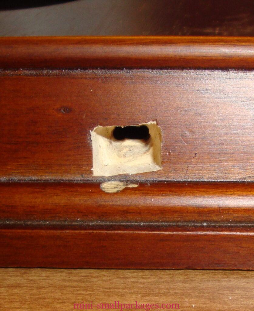
Yes, I made a boo-boo and will have to fix it. I also actually picked up the wrong switch and cut a hole for it. Only difference between them was this switch is shinier and slightly larger, but not really wrong.
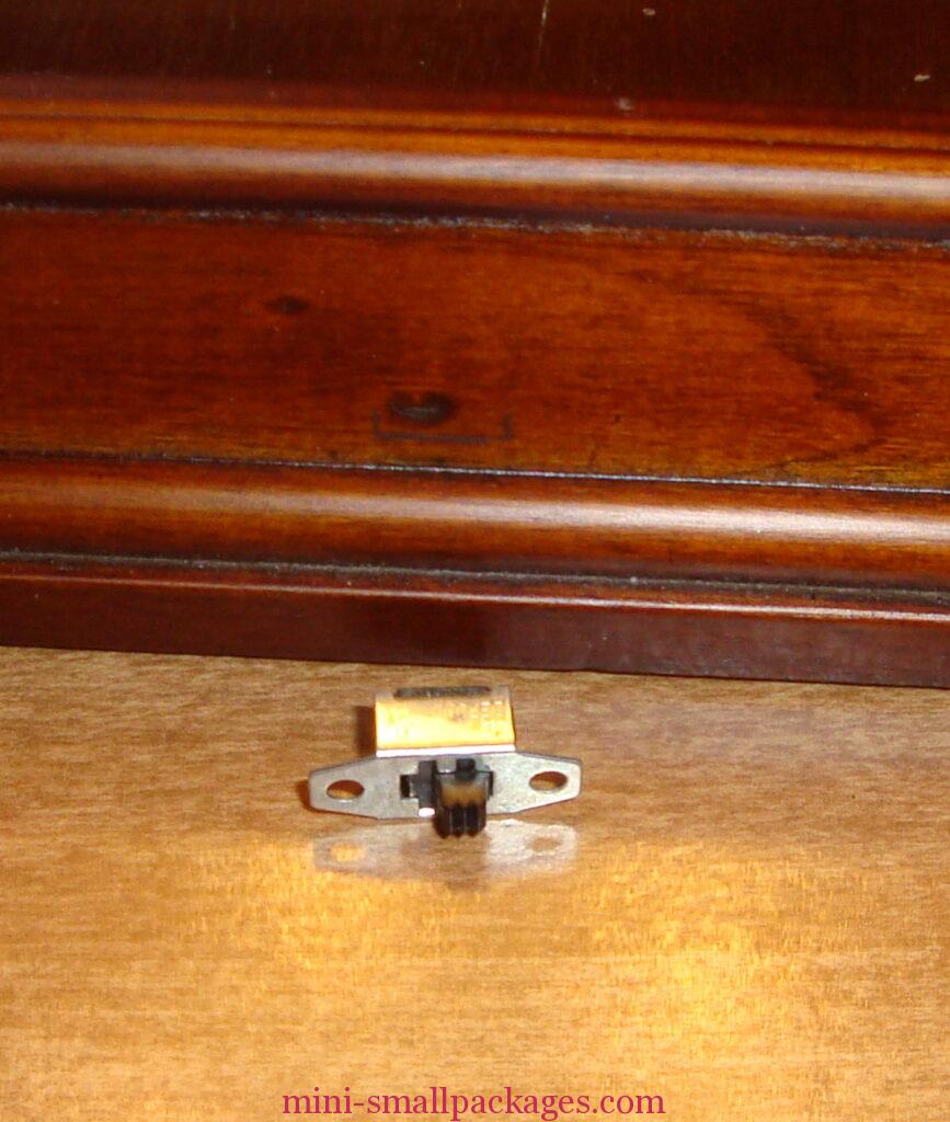
Now to connect the switch to some wires.
The switch has three legs and this particular one needed one wire to the middle leg and the other wire to an outer leg. Once it was soldered I slide the wires inside my base so I could get to them from the basketball hole.
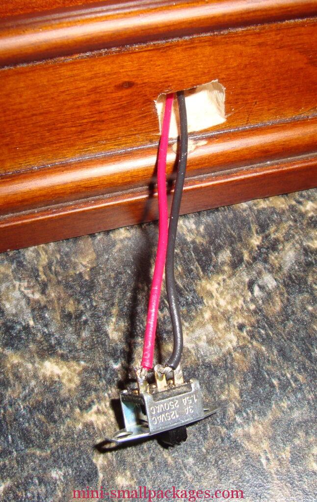
This pic isn’t the best, but the third leg on the right does not have a wire attached.
Next I drilled a hole in the back of the base for the wire to the transformer.
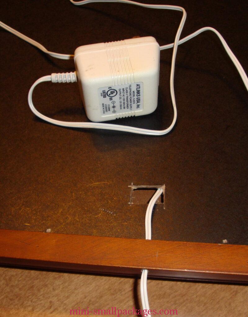
This hole only needed to go thru the bottom part of the base, but could have been in a similar position as the switch but for this base would have been a slightly harder hole to drill. I also choose to cut an opening in the extra board in the base so I could get to the basketball hole on the topside of the base. This opening could have been round instead.
The transformer that I am using is from a old phone. I purchased several of these at a thrift store. Just be sure they are rated for the lights used. Mine are 12 volt and this transformer plug is as well.
The next thing we checked is what are the mA of the output of the plug. This happened to be listed on the plug as 300 mA. If it wasn’t, then we would have used a meter to test this.
The 12v lights are labeled as 60 mA and I have 7 lights so this plug was the correct amount. (Per my husband who is my goto guy for electrical). 7 x 60 = 300. It is my understanding that too much would not be good and less just means the lights may last longer just not burn as bright.
Next I needed to connect the three sections of wires.
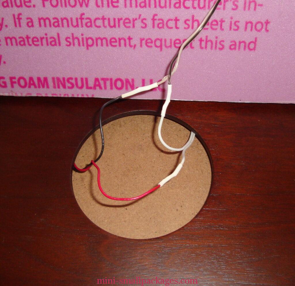
At the top of the pic are the two wires from the house base and the actual lights. One lead has all the leads from one side of the lights and the other lead has all the others.
The house wires are black and light colored wires are at the top of this pic.
The two white wires coming from the right side of the pic are from the transformer plug.
The black and red wires that are coming from the left side are to the switch.
One of the white wires from the transformer plug are soldered to a house wire.
The other white transformer plug wire is soldered to the red wire from the switch.
The black wire from the switch is then soldered to the light colored house wire.
These soldered connections make a circle of sorts.
Before soldering a connection the wires should be stripped of the outer covering. I do this carefully with a craft knife to cut though the plastic covering on one side and then fold it open and carefully cut against the side of the plastic again. This generally leaves a section of this covering still connected, but will tear away when pulled on. (I have added a wire stripper to my wish list.)
The wires if multiple are then twisted together so they are neat.
Then using a soldering iron and solder the wires get tinned. To tin touch the tip of the soldering iron to the wire and the solder just away from the tip but on the wires. When the heat makes the solder flow, then run the solder on the wires and it is tinned.
The switch has to be tinned a bit differently. The legs have holes in them. Same prinicple of touching the iron to the leg and the solder away from the tip and when the solder flows, then fill the hole.
Once the wires or legs are tinned then put aside the solder.
Now for wire to wire, I slide a heat shrink tube on one wire to be connected. This tube should be large enough to fit over both wires once soldered and long enough to cover the bare wires.
Set up the wires so they are touching (a third hand is helpful here) and can even bend them a bit to help then stay together while soldering.
Apply the heat tip to the two wires and let the tinning flow together.
Once soldered together, slide the heat shrink tube over the bare wires connection and apply heat such as a match or candle flame.
The switch was connected to each wire by touching the tip of the solder iron to the leg and holding the wire at the filled hole. When the solder begins to flow insert the wire in the hole. These will stick out and can be trimmed down close but not right next to the leg.
Now test the plug by plugging it in and flip the switch.
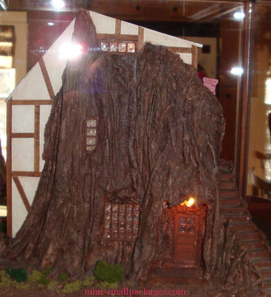
Here is my house lit up from the front and the back.
Using a battery such as a 9v instead of a transformer
The battery connection would be in place of the transformer leads.
I like to make a housing for my batteries and this basketball case would have worked for that if I wanted. Using the foam as my base, I could even cut a hole to accommodate the depth of the battery if needed.
Happy miniaturing!
Preble